
 en
en italiano
 čeština
 Deutsch
 français
 hrvatski
 magyar
 polski
 српски
 русский
 中文
中文 中文
中文 한국어
한국어 español
Extract Data

Ribbon: Output > Data > Data Extraction
Keyboard: DATAEXTRACTION
Alias: DX, EATTEXT
Extracts data from entities in one or more drawings and exports it to a table or external file.
Note: In addition to the classic data extraction functionality, progeCAD now offers an experimental, enhanced version of this powerful command, called DATAEXTRACTIONNEW. See the explanation in this section.
PROCEDURE:
Begin (Step 1 of 7)
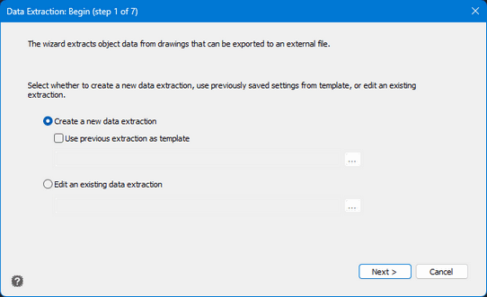
The program asks whether to create a new data extraction (COV file), optionally based on a previous extraction file used as a template, or to edit an existing data extraction.
Data Source (Step 2 of 7)
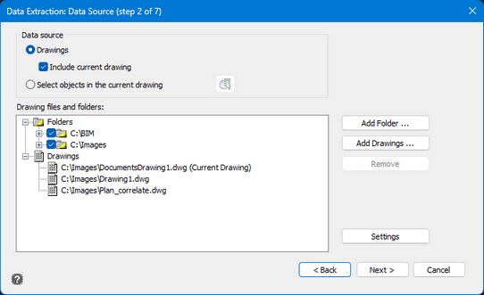
In this section, the data source is specified.
Data Source
It is possible to select Drawings as the source; in this case, you can specify whether to include the current drawing.When Select objects in the current drawing is chosen as the data source, it is possible to directly select the objects to be included in the extraction from the current drawing.
Buttons
Add folder: opens the Add Folder Options dialog, where you can specify the folders to include in the data extraction.
Add drawings: opens the standard File Selection dialog, where you can specify drawings to include in the data extraction.
Remove: removes the selected drawings or folders from the data extraction list.
Settings: opens the Data Extraction – Settings dialog, where data extraction settings can be specified. (These functions are not yet supported and are read-only.)
Note: The Add Folder and Add Drawing buttons are enabled only if the Drawings option is selected as the data source.
Drawing files and folders
The list shows all drawings and folders included in the extraction.
Right-click to access the context menu.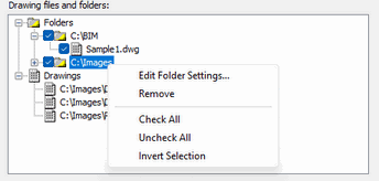
Edit Folder Settings: opens the Add Folder Options dialog, where folder settings for data extraction can be modified.
Remove: removes the selected folder from the data extraction list.
Check All: selects all drawings.
Uncheck All: deselects all drawings.
Invert Selection: reverses the selection of items.
Right-clicking a drawing within a folder allows you to select, deselect, or invert the selection of drawings in that folder.
Select Objects (Step 3 of 7)
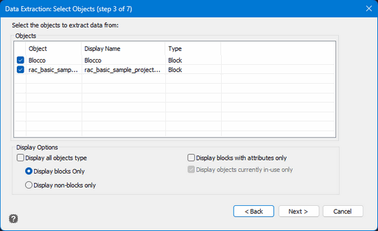
This section shows the items found in the drawings chosen for data extraction. All items are selected by default, but you can change the selection by checking or unchecking the blue box.
The table displays the found objects, their displayed name, and the object type (Block or Non-Block). Click a column header to reverse the sorting order. Columns can also be resized.
Display Options
Select Display all objects type: this option is selected by default and allows all objects to be displayed. If it is not selected, you can choose to display only Blocks (Display blocks Only) or only Non-Block objects (Display non-blocks only).
Display blocks with attributes only: shows only blocks that contain attributes.
Display objects currently in-use only: disabling this option is not yet supported.
Select properties (Step 4 of 7)
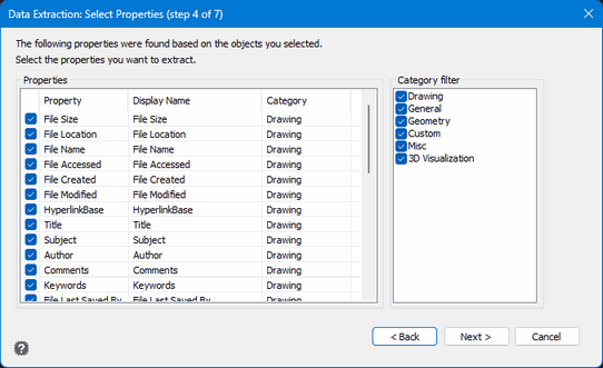
The list shows every property of the objects previously selected, allowing you to choose which properties to include or exclude. Click a column header to reverse the sorting order. Columns can also be resized.
Use the Category Filter to filter the list of properties according to the chosen category.
Right-clicking anywhere in the table allows you to select, deselect, or invert the selection of the listed properties.
Refine Data (Step 5 of 7)
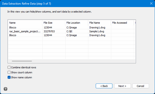
This section allows you to customize the data extraction table by showing or hiding columns and reordering them according to the selected columns.
Click a column header to reverse the sorting order. Columns can also be resized.
Choose Output (Step 6 of 7)
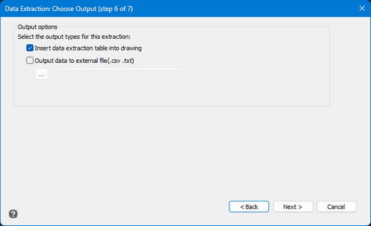
Specifies the type of output for the extracted data.
You can insert the extracted data as a table directly into the drawing. The insertion point is requested at the end of the procedure.
Alternatively, you can export the extracted data to an external file in .CSV or .TXT format. Clicking the "... " button opens the standard File Selection dialog box.
The external file is created at the end of the extraction procedure.
You can select both options.
Finish (Step 7 of 7)
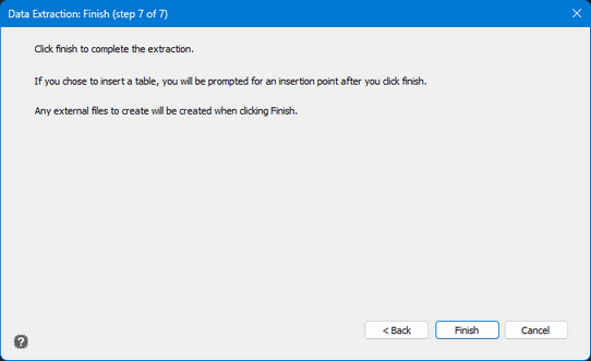
Click Finish to complete the data extraction.
If, in the previous step, you chose to insert the table into the drawing,
you will be prompted to specify the insertion point.
If you chose to create an external file instead, the file will be generated
automatically.
Keyboard: DATAEXTRACTIONNEW
Alias: DX, EATTEXT
How to use it:
Method 1: Every time you need to export, type the DATAEXTRACTIONNEW command.
Method 2: Type DATAEXTRACTIONMODE and change the value to 2 then restart progeCAD. From now on, DATAEXTRACTION starting by default from menus will be the New Data Extraction. If you need to use the Classic Data Extraction, change the value again to 1 or type the command DATAEXTRACTIONCLASSIC.
DATAEXTRACTIONNEW has new functions and the ability to create dynamic tables inside the drawing that can be updated based on drawing changes.
DataExtraction hot features:
• Xrefs and Blocks inside Xrefs extraction
• AEC Objects data extraction
• Optional filter for Layouts (Paper Space) and Models
• Custom rename of Columns
• Customize Columns Order
• XLS and XLSx export supported
• Selectable styles for tables
• Extracted tables are dynamically linked to the drawing and automatically updated with drawing changes through the DATALINK functions
BEGIN (Page 1)
Create New Report Template Select to extract data and create a report based on a new report template. When you click Next, the Save Data Extraction As dialog box displays where you enter a name for the new report template (.idxe) file.
Start with Existing Report Template Mark to create the new report template based on an existing one. Click [...] to select the report template (.idxe) file that has the settings you want to use in the new report template, save it with a new name and optionally modify when continuing.
Edit Existing Report Template Select to extract data and create a report based on an existing report template. Click [...] to select the report template (.idxe) file that has the settings you want to prefill and optionally modify when continuing.
Reuse Existing Report Template Select to extract data and create a report based on an existing report template without modifying it. Click [...] to select the report template (.idxe) file that has the settings you want to use for data extraction.
DEFINE DATA SOURCE (Page 2)
Drawings Select to extract data from all entities in the drawings and folders you specify.
Include Current Drawing Mark to extract data from entities in the current drawing. If additional drawings or folders are selected, the current drawing may contain no entities.
Select Entities in the Current Drawing Select to extract data only from entities in the current drawing. Click () to switch to the drawing temporarily and select the entities that you want to extract data from. If this option is selected, the next three options are unavailable.
Drawing Files and Folders Lists the folders and drawings to extract data from.
Add Folder Click to select a folder that contains the drawing files to extract data from. After you select the folder, the Add Folder Options dialog box displays where you can specify additional options for adding files.
Add Drawings Click to select a drawing file to extract data from.
Remove Click to delete the selected drawing file from the Drawing Files and Folders list.
Settings Click to open the File Type Settings dialog box where you can specify which entities to extract data from.
SELECT ENTITIES (Page 3)
Entities Lists all entity types available for data extraction based on the source files selected on the previous page. Mark the entity types you want to include in the report. The Display Name is prefilled with the name of the entity and can be edited.
Display All Entity Types Mark to include all entity types in the Entities list. When unmarked, the following options are available:
- Display Blocks Only Select to include only blocks in the Entities list.
- Display Non-Blocks Only Select to include all entity types except blocks in the Entities list.
- Display Blocks with Attributes Only Mark to include only blocks with attributes in the Entities list. Not available when Display Non-Blocks Only is selected
SELECT PROPERTIES (Page 4)
Properties Lists all properties available for data extraction based on the entity types selected on the previous page. Mark the properties you want to include in the report. Each row displays a property, its display name (which can be edited), and category.
Category Filter Lists categories based on the available properties. Mark the categories of properties that you want to display in the Properties list.
REFINE DATA (Page 5)
Report Preview Displays a preview of the data to be inserted as a table in the drawing or saved to an external file. You can modify the table structure as needed, e.g., click and drag columns to reorder them, or click a column name to sort column data in ascending or descending order. You can also right-click a column to choose more options, e.g., hide and unhide columns, refine data further using the Filter Column dialog box, or remove filters from columns.
Combine Identical Rows Mark to include only one row for rows with identical data. If marked, the Count column updates with the sum of all combined rows.
Show Count Column Mark to display the Count column in the report preview and include it in the report.
Show Name Column Mark to display the Name column in the report preview and include it in the report.
CHOOSE OUTPUT (Page 6)
Insert Report Data As Table in Drawing Mark to create a table containing the extracted data. If marked, you are prompted for an insertion point in the drawing after you click Finish on the Finish page.
Output Report Data to External File Mark to create an external .xls or .csv file containing the extracted data. Click [...] and in the Save As dialog box, specify a name, file location, and file format for the external file.
TABLE STYLE (Page 7)
This page displays only if you chose to insert report data as a table in the drawing.
Table Style Choose a table style from the list of table styles
available in the current drawing, or click ( ) to
open the Table Styles
Manager dialog box.
) to
open the Table Styles
Manager dialog box.
Title Cell Style Choose a cell style for the title cell.
Header Cell Style Choose a cell style for header cells.
Data Cell Style Choose a cell style for data cells.
Use Property Names as Additional Column Headers Mark to include a header row with display names of properties that were specified on the Select Properties page.
FINISH (Page 8)
Click Finish to extract data and output it to a table in the drawing and/or an external file.
Tell me about...
How do I...
Reporting information about entities